Previously, I looked at the data interface of a SunnyBoy inverter. Since we now know the pinout, we can attempt at building our own interface board. To make our life simple, it would be nice to get it to be USB, so we don't have to mess around with RS485 or RS232 adapters.
Considerations for the USB Interface
USB uses differential signalling at a speed at depends on the version. While the inverter itself uses a relatively slow baud rate, our electrical interface still needs to be good enough for USB. If we want to use the existing screw terminals to connect the wires, USB3 is not going to work, so we want to aim at an UART to USB converter IC that uses as old or slow of an USB version as possible.
The popular cheap option - the CH340 series - is an USB full speed device, so USB 1.1 with 12 Mbps. Maybe we can get away with the screw terminals. Otherwise we have to use a proper USB connector.
Since USB also provides 5V power, we do not need an isolated DC-DC power supply. Instead, we can just use the power provided by USB.
Isolation
The manufacturer-designed PiggyBack modules use a combination of ESD protection diodes, resistors and optocouplers to isolate the data signals. Another option is to use dedicated digital isolation ICs. We however have to be a bit careful about what part we select. The cheap, widely available SOIC-8 parts often have weak or no input protection and a 560V rating for the working voltage. They tend to have a higher peak isolation voltage rating, but can only survive that for short amounts of time. We need more than 600V isolation sustained.
There are also higher rated parts with integrated ESD protection, for example the TI ISO7721DWR. It comes in a wider package to also increase the creepage distances around the body of the part. It only needs one external part: A 0.1 uF capacitor on the power pins for each side.
Circuit
So, given the choice of digital isolator and TTL-to-USB converter IC, we can put together a simple circuit based on the recommended external parts in their respective datasheets:

Since the ISO7721DWR already has ESD protection integrated, we do not need external resistors or ESD diode arrays. A 100nF decoupling capacitor is recommended on each side though.
Likewise, the CH340N includes an oscillator and all required resistors for USB, so there we also get away with just adding some power supply decoupling.
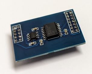
PCB
Due to the low part count, the PCB is quite trivial:


The only slightly noteworthy thing is that the ground planes on the back have a nice separation gap between them. Otherwise we'd be circumventing the isolation the ISO7721DWR provides. Even with the solder mask, the isolation should be good enough for 1000V.
Getting the Boards built
I like the integration between lcsc.com, easyeda.com and jlcpcb.com for quick prototypes - you get the symbols and footprints directly via the part-number and ordering PCBs with or without assembly is just a few clicks. So I used them here as well - you could of course achieve the same with KiCad and some other manufacturer.
At the time of writing, 5 PCBs cost $3.10 and parts for 4 boards $10.69. Shipping and handling for both (old customers get a discount on LCSC when also ordering from JLCPCB) came out to $11.56. This is quite a bit less than what even a single second-hand RS485 piggy back sells for.
I also ordered some insulating silicone tube and cable glands which came out to ~$5 per inverter.
Testing
If you're following along and want to install a similar board, please keep in mind that the inverter has mains voltage and the full PV string voltage present. This can be hundreds of volts DC. Disconnect the inverter completely and let capacitors drain. If in doubt, hire a certified electrician to do the work.
Also, keep in mind that the design presented in this article is the work of an amateur and has not been tested or certified by any authority or lab. I cannot guarantee that it is safe and does not burn down your house.
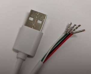
With the parts soldered, we're ready to test if the gamble with USB 1.1 over the screw terminals worked out. While just chopping off one end of an old USB A to mini or micro USB cable would be enough, I'd recommend putting ferrules on the exposed ends. Otherwise the screw terminals can easily break the thin strands for the D+ and D- signal wires.
USB can be tested even with the inverter turned off - since the required power is provided via USB as well. And it indeed looks like the CH340N works just fine hooked up to a Raspberry Pi.
With everything closed up and the inverter powered up, we can try to read out some values.
SMA provides an open source library to interface with their devices called
YASDI. After building the library
with the instructions supplied with the SDK, we can use the yasdishell executable
to test. For that, we first need to create a yasdi.ini config file:
[DriverModules]
Driver0=yasdi_drv_serial

[COM1]
Device=/dev/ttyUSB0
Media=RS232
Baudrate=1200
Protocol=SMANet

[Misc]
DebugOutput=/dev/stdout
It does not seem to make much of a difference whether we use RS232 or RS485 as the media.
In yasdishell, scan for devices and get spot values as per the built-in help.
Conclusion
With this, we have a working, simple way of getting stats out of old inverters. To process the data further, one can for example use github.com/pkwagner/yasdi2mqtt to publish measurements to MQTT. I'm then using my InfluxDB-Telegraf-Grafana stack I use for other things to also store and visualize the inverter data.