From poking around earlier, we can make an educated
guess that the graphical output works via frame buffer as there is a device node
/dev/fb0. fbset can tell us a bit more about its format:
<root@rigol>fbset

mode "1024x600-0"
        # D: 0.000 MHz, H: 0.000 kHz, V: 0.000 Hz
        geometry 1024 600 1024 600 16
        timings 0 0 0 0 0 0 0
        accel false
        rgba 5/11,6/5,5/0,0/0
endmode
So we have 1024 * 600 pixels formatted as 16bit RGB values with 5, 6 and 5 bits respectively dedicated
for the colors.
Let's try dumping the frame buffer (cp /dev/fb0 /tmp/screenshot) and transfer it over
to our more beefy Ubuntu VM. There, we can use ffmpeg to convert it to PNG:
$ ffmpeg -vcodec rawvideo -f rawvideo -pix_fmt rgb565 -s 1024x600 \
         -i screenshot -f image2 -vcodec png screenshot.png
Looking at the resulting file, we however just see the RIGOL logo with the loading progress bar at 100%, so there seems to be more to it. The easiest way to figure out how the frame buffer works would be to look at the source - fortunately, Olliver Schinagl managed to get kernel sources from Rigol and put them on GitLab.
The frame buffer driver
Looking at .config we find that
the only enabled frame buffer driver is CONFIG_FB_XILINX. This driver can be found in
/drivers/video/xilinxfb.c.
After the normal header includes, this driver also seems to just straight up include
/drivers/video/dpu.c.
An interesting place to start is probably the ioctls this driver supports as there might be some special ones Rigol put in. And we can indeed find some custom commands in xilinx_fb_ioctl:
DPU_SET_LAYER_RST: Resets the driverDPU_SET_LAYER_ID: Changes the layer IDDPU_GET_LAYER_ID: Returns the current layer IDDPU_SET_TRACE_MASK: ???DPU_SET_TRACE_COLOR: ???DPU_SET_TRACE_DATA: ???DPU_SET_LAYER_ALPHA: ???DPU_SET_LAYER_OPEN: ???DPU_SET_LAYER_CLOSE: ???DPU_SET_WAVE_XY: Set the X and Y coordinate of the wave layerDPU_SET_HDMI: ???DPU_SCR_PRINT: Instruct the hardware to do a printscreen
The command numbers start with 0x0F000000 for DPU_SET_LAYER_ID and then just increment in the order defined
in the enum in
/drivers/video/dpu.h
(note that the order is slightly different than above / in the ioctl code!).
Layers
So it seems we have a stack of layers. drvDPUInit provides a good idea of what these layers are. The layer numbers are defined via an enum:
enum
{
    DPU_Layer_Back,  // layer 0
    DPU_Layer_Wave,  // layer 1
    DPU_Layer_Eye,   // layer 2
    DPU_Layer_Fore,  // layer 3
    DPU_Layer_Print, // layer 4
    DPU_Layer_Comp,  // layer 5
    DPU_Layer_All,
    DPU_Layer_Logo = DPU_Layer_All
};
DPU_Layer_All does not seem to be a layer itself but is used as the number of layers (of which there are 6).
How do we get those layers? The memory that is mapped in
xilinx_fb_mmap
is chosen based on drvdata->opAddr which indexes to the layer currently chosen via the DPU_SET_LAYER_ID ioctl.
We can thus use said ioctl to select which layer we want to mmap.
Dumping layers
To dump layers, we have to switch the layer via ioctl, mmap the file and then just write out the bytes.
We can again use ffmpeg to convert the raw pixel array to a PNG file.
You can find my rust implementation for the dumper on Github. It
also contains code to directly output PNG, so you can even skip ffmpeg.
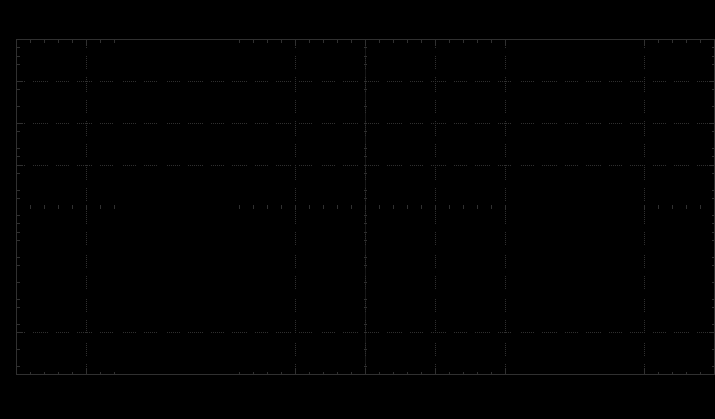
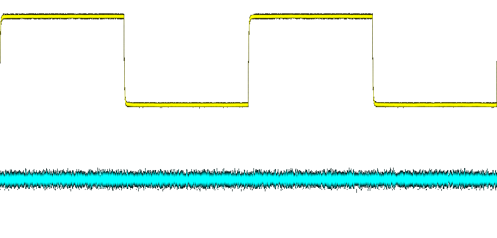
The background (0) and foreground (3) layers contain about what we'd expect, namely the backing grid and
the UI elements respectively. The wave layer has a different color format and dimension - the code indicates
1000 * 480 in R8G8B8 format. The reality seems to look different though if we look at an excerpt from hexdump:
000e6b90  cc cc cc 00 00 45 45 00  cc cc cc 00 00 45 45 00  |.....EE......EE.|
000e6ba0  00 6a 6a 00 cc cc cc 00  cc cc cc 00 00 53 53 00  |.jj..........SS.|
We know that the transparency color is 0xCCCCCC so we have 4 bytes with the 4th always being zero.
Additionally, the trace is yellowish, but the first byte is zero for opaque pixels. So this looks
more like a BGR format with 1 byte each + a zero-byte per pixel.
Taking screenshots
From the code, we can also deduct that there is a hardware-assisted print screen function. The implementation can be found in the printSCR function. It seems to set a register to request the operation and then wait until completion is signalled via another register or the timeout expires.
We can trigger this by using command 0x0F00000C and passing a pointer to an integer - this will contain
0 to signal success and 1 for failure.
Putting it all together
With the separate layers, we can do custom stackups. The following image is the back layer with the wave layer on top as two images. Since we have transparency preserved in the PNG files, this works as intended and shows the background grid under the traces: